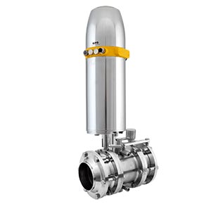
Leakage double-butterfly valves
Sanitary Valves
Safe and adaptable
Increased safety with Guth leakage double-butterfly valves

Features and Benefits
Safe and cost-effective
Guth leakage double-butterfly valves are the cost-effective solution for safe product separation in process plants. With two flaps separated by a leakage space, they offer extra safety in areas where contamination is critical. Switching is done using a handle, which switches both flaps simultaneously via a mechanism. They are used as reliable shut-off elements on panels, containers and pipelines. A leak caused by seal wear can be detected and corrected immediately.
Guth leakage double-butterfly valves are also available in the maintenance-friendly intermediate flange design. This design allows the seals to be exchanged with little effort and quickly.
Modular for individual solutions
Of course, you do not have to do without automation in this cost-effective leak-proof valve sector. Our modular system makes it possible to change over quickly and easily from manual to pneumatic drive without removing the valves from the piping system. The drives are available with sensors or control head KI-TOP. Guth pneumatic rotary actuators are characterised by a particularly high torque. The closed version in stainless steel housing is completely maintenance-free. We give you a 5-year guarantee. The standard position indicator lets you know at any time how the valve is switched. The practical end position detector ensures permanently reliable feedback without the hassle of readjusting the limit switches. Our pneumatically driven leakage butterfly valves can be equipped with sensors or KI-Top control heads.
- Cost-effective leakage protection
- Hygienically safe due to easy cleaning of the leakage chamber
- Easy to install
- Simple and compact design
- Maintenance-friendly construction in intermediate flange design
- Fully automatable PLC or ASI bus
- Stainless steel handle
- Actuators selectable, two power levels
- Sealing materials EPDM, HNBR, FKM, silicone
Technical Specifications
DN 10–DN 150 1″–4″ intermediate flange up to DN 200
EPDM HNBR Silicone FKM
SIP 140°C, 30 min SIP 100°C, 30 min SIP 110°C, 30 min SIP 90°C, 30 min
in product contact
1.4301 / AISI 304 1.4307 / AISI 304L 1.4404 / AISI 316L
Ra ≤ 0.8 µm
PDA 75 / PDA 100 / PDA 125
DN 15–65 / 1″-2½” DN 80-100 / 3″–4″ DN 125 / 150 / 200
max. 16 bar max. 10 bar max. 6 bar
5.5–8 bar lower control air pressures on request
95° C
S-S two-sided welded connection G-S threaded-/welded connection K/M-S cone nut-/welded connection K/M-G cone nut connection/thread FL. PN 10-G flange PN 10/thread Cl-Cl clamp/clamp connection RJT threaded nozzle (special socket)

